UNDERGROUND TRANSFORMER STATIONS
For the modernisation of urban centres
GRITEC Underground Transformer Station is mostly involved in upgrades of electrical distribution systems in historical city centres. They preserve the original architectural value of a city, and allow pedestrians to move around the location of the transformer station continuously.
Underground, the transformer stations are affected with various impacts,
which are not present in surface transformer stations. In more than 60 years, it
has been proved that our transformer stations safely resist these impacts,
and provide our customers with long-term reliable operations.
RESISTANCE AGAINST EXTERNAL INFLUENCES
Resistance Against Underground Water
Seamless concrete body of the transformer station is perfectly watertight. The concrete with the given exposure class can resist both chemically aggressive environment influences, and the pressure of the underground water. If the station is exposed to the effects of the underground water under pressure, and the water level is above its basement joint, the concrete body is welded through stainless steel pads to the foundation ballast slab. The cable transits are sealed with special sealing grommets and sealants.
Resistance Against Rain Water and Snow
The rain water is drained from ventilation shafts to sewerage or a seepage sump. When connected to the sewerage, a clack valve is installed accessible from outside of the station. Snow and ice in the ventilation shafts melt due to the waste heat flow from the transformer.
Protection Against Rodents and Burglary
We use special ventilation elements manufactured in our own locksmith’s
shop. Within the design and production phase of the elements, we focus on
their increased protection against rodents and insects. In order to replace
the transformer, the cover can only be lifted with a crane due to its great
weight. An integrated operating personnel entrance is secured with a lock.
Protection Against Noise
The underground installation of the station is the most suitable for noise reduction.
Carrying Capacity
The 200 mm thick cover reinforced concrete slab has sufficient load carrying capacity for a travelling truck. Optionally, we can design the cover slab
for an extreme load, as defined by the customer.
ELECTRICAL TECHNOLOGY
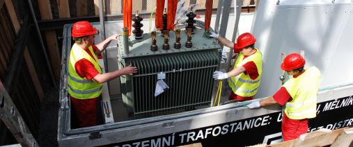
We generally install transformers in under- ground
stations, with an output up to 2.5 MVA. In special
design cases, the transformer output can be even
higher. Both oil and dry transformers are usually
placed on a concrete floor, allowing for oil drainage,
and in case of their replacement, if applicable, they
can be replaced after removing the cover. There is
an oil sump ready below the transformer.
HV and LV switchgears are located on an intermediate floor of a switching station, which can be separated from the transformer chamber with a partition wall. HV switchgears with a voltage of up to 35
kV can be compact or modular units, insulated with
SF6 gas or air. LV switchgears are cabinet or wall
structures and they can be used for high nominal
currents up to 3612 A.
Robust patented cable grommets allow for routing
all standardized cables used in electrical engineering. Optionally, grommets of other manufacturers
can be supplied.
SAFETY
Health and property protection is of high priority to us. Our products meet all the requirements, as set by standards and regulations. Thanks to our innovative solutions, we are able to offer even greater protection and safety as an option.
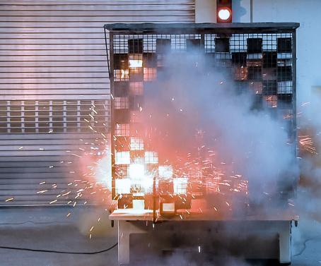
Fire protection assessment of civil structures
| CONSTRUCTION | REQUIRED RESISTANCE AS PER EN 730802 | REQUIRED RESISTANCE AS PER EN 61936-1 | USED MATERIAL | REAL RESISTANCE | EVALUATION |
|---|---|---|---|---|---|
| Enclosure walls | REW 15 | REW 60 | Reinforced concrete, min. thickness 140 mm | REW 90 | Satisfied |
| Fire protection ceiling | REI 15 | REI 60 | Reinforced concrete, min. thickness 200 mm | REI 90 | Satisfied |
GRITEC CONCRETE PRODUCTS
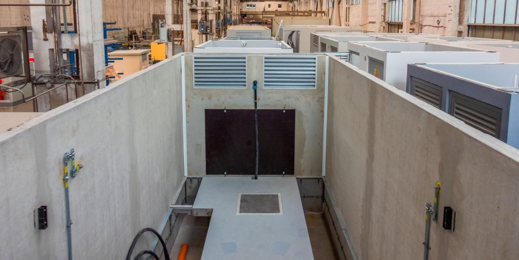
The body of the station is made of 4 mostly 14 cm
thick enclosure walls and a usually 20 cm thick bottom. We cast it as a single piece, using a process of
called bell casting. This method of production provides the body with the following properties:
- exceptional mechanical resistance; the body is a self-supporting box element, which does not require any basement in most cases,
- perfect tightness; the monolithic and seamlessly casted concrete body is watertight, and at the same time, it is used as an oil leak-proof sump in case of transformer failure,
- easy transportability, resulting again from the body‘s mechanical stability,
- long-term lifetime and reliability.
We manufacture the body, the covering ceiling slab and partition walls from watertight construction concrete with C35/45 strength class, and XC4 and XF1 exposure class as per EN 206+A1.
There is an inspection and installation entrance in the cover slab. The operating personnel can enter the station through the access cover, which has integrated railings on the inside to provide protection against anyone falling in. The station is also equipped with a steep stairway, or more frequently, with a ladder. The installation cover to replace the transformer is equipped with eyes to grip ropes.
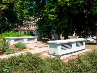
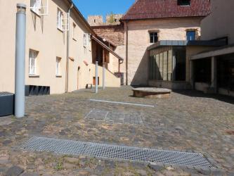
Ventilation shafts are also made from monolithic concrete as part of the body. The shafts can be terminated at terrain level with a horizontal grid, or they can be routed above terrain level using so called necks, and equipped with vertical grids on their sides.
We make a concrete false floor in underground stations, either across the whole area, or in the transformer replacement route only. The concrete intermediate floor can be combined with an aluminium profiled floor on less loaded parts. The advantage of the concrete intermediate floor is its incombustibility and high carrying capacity, the aluminium profile system is excellent with its high flexibility. We install the aluminium profiles on adjustable zinc-coated steel supports. The stepping layer is made from plywood provided with a slip-resistant finish. These boards are equipped with a key operated latch to prevent them from being lifted.
The partition walls can be removed, or mobile, and equipped with a door, too. We make these partition walls from aluminium alloys.
LOCKSMITH PRODUCTS
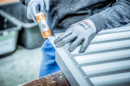
We make the ventilation elements in our own METALLBAU locksmith shop from anodized aluminium. This material has a corrosion resistance, and similar stability as the concrete used for the structure body.
TYPES AND DIMENSIONS OF UNDERGROUND TRANSFORMER STATIONS
GRITEC underground transformer stations with UW type marking are provided in a large variety of types, which are derived from basic module lines UW 25 (width 2.58 m), UW 30 (width 3.06 m), UW 33 (width 3.36 m) and UW 36 (width 3.66 m). With a constant width, the external length varies from 2.46 to 8.46 m in a 0.6 m grid. The dimensions provided are applicable for a 140 mm thick wall.
As standard, the cell is delivered with a headroom
of 3.2 m, whereas, if the intermediate floor is used,
the headroom of the switching station is 2.4 m and
the height of the cable space is 0.8 m including the
floor. Other dimensions are available as requested.
INSTALLATION
To speed up the installation, we install the electrical technology in the station at the production plant.
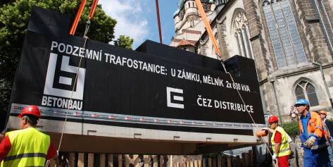
We put the station itself on a prepared gravel base layer without foundations. Foundations are required only in demanding geological conditions, or for combined buildings composed from multiple bodies. We transport the underground stations as an excessive load, and install it with a crane. The underground station weight, including accessories, is 13 to 50 t.
The customer provides geological survey, excavation work including formwork, preparation of the
construction base, external cables and external
earthing. The excavation work must be coordinated with conservationists and archaeologists. The
excavation pit formwork must be dimensioned
for the movement of heavy machines in the close
surroundings (min. 90 t). If the underground water
level is above the construction trench, a basement
load slab must be made as protection against the
underground water upward pressure. Then, the station is welded to this slab using stainless steel pads.
INCORPORATION INTO THE TERRAIN
The transformer station can be covered with paving, gravel, mastic asphalt, or green grass.



OPERATION AND SERVICE
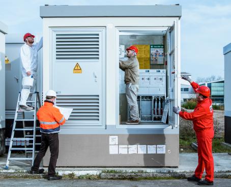
We provide a comprehensive service for our transformer stations during maintenance, redevelopment and upgrades.
We will find the optimal solution for your project. Ask our sales and technical representatives for advice or a no-obligation price offer.


