WALK-ON TRANSFORMER STATIONS
Substations With Indoor Service
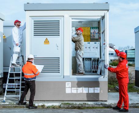
GRITEC walk-on substations can meet even the most demanding requirements. We fit them with 4.8 MVA transformers, and even more powerful ones for special projects. The stations are a walk-in design, accessible from inside for operating personnel. Due to their dimensions,the stations form a distinctive feature in a built-up or rural area. For that reason, we offer a range of surface finishes and technologies for conveniently blending the buildings into their settings.
SUMMARY DESCRIPTION AND COMPARISON WITH THE COMPACT SUBSTATIONS
| STATION TYPE AND CODE | WALK-ON | COMPACT |
|---|---|---|
| GRITEC model series code | UF | UK |
| Operator access | walk-in | non walk-in |
| Height from ground | approx. 2.8 m | approx. 1.5 m less than 1m for underground (or, half-buried) stations |
| Footprint | approx. 6–25 m2 | approx. 3–6 m2 |
| Weight, equipment exclusive | 13–50 t | 7–13 t |
| Transport | oversize load | common road truck |
| Transformer output power | up to 4.8 MVA, or more depending on project | normally 630 kVA, up to 2.5 MVA depending on project |
| Transformer placed on | rails | on transformer station floor |
| Transformer replacement | through door | following roof dismantling |
ELECTRICAL TECHNOLOGIES
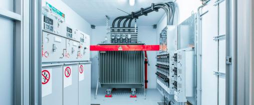
As a rule, 4.8 MVA transformers are used to fit out the walk-on stations. The transformer output power may be increased for special projects. Oil and dry transformers are normally placed on steel sections (transformer rails) and their potential replacement is executed through the transformer vault door. An oil retention pit is ready under the transformer.
Robust, patented cable grommets serve as passthroughs for all standardised cables used in the power engineering industry. Grommets from other manufacturers may be supplied upon request.
The HV and LV switchgears are placed on the raised
floor of the substation that is as a rule separated by
a concrete partition wall from the transformer vault,
and accessible through a separate door. The HV
switchgears up to 35 kV voltage may be both compact and modular, and SF6 gas or air insulated. The LV
switchgears are a cabinet or wall-mounted design and
may be deployed at high rated currents up to 3,500 A.
The measuring boxes (USMs, universal measuring boxes) are installed in the external wall cutouts, thus providing for their accessibility also from the outside.
BUILDING AND STRUCTURAL SOLUTION
The body of a station is comprised of 4 external walls, at a minimum thickness of 10cm, and a bottom at a minimum thickness of 12cm. We precast the body using the “bell casting” method, as a single seamless casting. The manufacturing method gives the following features to the body:
- exceptional mechanical resistance. The body is a self-supporting box type element and, as a result, it needs no foundation and may also serve as a retaining wall when set in a slope
- perfect tightness; the cast-in-place, seamlessconcrete body is watertight, serving at the sametime as an impermeable pit to catch oil in case ofa transformer accident,
- easy transportability, based again on the mechanical stability of the body itself,
- long service life and reliability.
We make the body, roof and partition walls from impermeable concrete of C35/45 strength class and
XC4 and XF1 exposure classes compliant to EN 206-1.
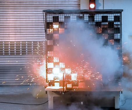
The roofs may serve also for ventilation and for overpressure exhaust in case of internal short circuit. As is standard, we fit the transformer stations with a flat reservoir roof that may be additionally vented along its perimeter. Upon request, we will execute any sloped roof solution with clad or sheet metal roofing.
The false floor is executed either from concrete or using an extruded aluminium shape system. The concrete raised floor benefits from being fire safe, while the aluminium shape system offers a high degree of flexibility. We mount the aluminium shapes on adjustable galvanised steel supports. The tread layer is of plywood with self-extinguishing and slip resistant surface treatment. The floor panels are fitted with a key operated latch preventing their accidental lifting.
The partition walls are at least 8 cm thick, while their
actual thickness and position are optional.
IRONMONGERY PRODUCTS
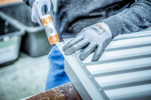
We make the doors and ventilation elements from anodized aluminium in our in-house METALLBAU machine shop.
TYPES AND DIMENSIONS
Type series UF 25
| Typ | L inner [m] | B inner [m] | H inner [m] | L outer [m] | B outer [m] | H* outer [m] | Zastav. plocha [m²] | Enclosed area [m³] | Weight [t] |
|---|---|---|---|---|---|---|---|---|---|
| 2524 | 2,18 | 2,30 | 3,20 | 2,38 | 2,50 | 3,32 | 5,95 | 20,35 | 14,51 |
| 2530 | 2,78 | 2,98 | 7,45 | 25,48 | 16,65 | ||||
| 2536 | 3,38 | 3,58 | 8,95 | 30,61 | 18,78 | ||||
| 2542 | 3,98 | 4,18 | 10,45 | 35,74 | 20,91 | ||||
| 2548 | 4,58 | 4,78 | 11,95 | 40,87 | 23,05 | ||||
| 2554 | 5,18 | 5,38 | 13,45 | 44,65 | 25,18 | ||||
| 2560 | 5,78 | 5,98 | 14,95 | 49,63 | 27,31 | ||||
| 2566 | 6,38 | 6,58 | 16,45 | 55,49 | 31,74 | ||||
| 2572 | 6,98 | 7,18 | 2,54 | 18,24 | 60,55 | 35,08 | |||
| 2578 | 7,58 | 7,78 | 19,76 | 65,61 | 37,50 | ||||
| 2584 | 8,18 | 8,38 | 21,29 | 70,67 | 39,92 |
* Outside height without roof plate.
Type series UF 30
| Typ | L inner [m] | B inner [m] | H inner [m] | L outer [m] | B outer [m] | H* outer [m] | Built-up area [m²] | Enclosed area [m³] | Weight [t] |
|---|---|---|---|---|---|---|---|---|---|
| 3024 | 2,18 | 2,78 | 3,20 | 2,38 | 2,98 | 3,32 | 7,09 | 24,25 | 16,57 |
| 3030 | 2,78 | 2,98 | 8,88 | 30,37 | 18,90 | ||||
| 3036 | 3,38 | 3,58 | 10,67 | 36,49 | 21,23 | ||||
| 3042 | 3,98 | 4,18 | 12,46 | 42,61 | 23,56 | ||||
| 3048 | 4,58 | 4,78 | 14,24 | 48,70 | 25,89 | ||||
| 3054 | 5,18 | 5,38 | 16,03 | 54,82 | 30,11 | ||||
| 3060 | 5,78 | 5,98 | 17,82 | 60,94 | 32,65 | ||||
| 3066 | 6,38 | 6,58 | 19,61 | 67,07 | 35,19 | ||||
| 3072 | 6,98 | 7,18 | 3,02 | 21,68 | 74,58 | 38,90 | |||
| 3078 | 7,58 | 7,78 | 23,50 | 80,84 | 41,53 | ||||
| 3084 | 8,18 | 8,38 | 25,31 | 87,07 | 44,17 |
* Outside height without roof plate.
Type series UF 33
| Typ | L inner [m] | B inner [m] | H inner [m] | L outer [m] | B outer [m] | H outer [m] | Built-up area [m²] | Enclosed area [m³] | Weight [t] |
|---|---|---|---|---|---|---|---|---|---|
| 3342 | 3,98 | 3,08 | 3,20 | 4,18 | 3,28 | 3,32 | 16,00 | 55,04 | 25,60 |
| 3348 | 4,58 | 4,78 | 3,32 | 16,00 | 55,04 | 29,81 | |||
| 3354 | 5,18 | 5,38 | 17,99 | 61,89 | 32,55 | ||||
| 3360 | 5,78 | 5,98 | 19,99 | 68,77 | 35,28 | ||||
| 3366 | 6,38 | 6,58 | 21,98 | 75,61 | 38,02 | ||||
| 3372 | 6,98 | 7,18 | 23,97 | 82,46 | 40,76 | ||||
| 3378 | 7,58 | 7,78 | 25,96 | 89,30 | 43,50 | ||||
| 3384 | 8,18 | 8,38 | 27,95 | 96,15 | 46,24 |
Type series UF 36
| Typ | L inner [m] | B inner [m] | H inner [m] | L outer [m] | B outer [m] | H outer [m] | Built-up area [m²] | Enclosed area [m³] | Weight [t] |
|---|---|---|---|---|---|---|---|---|---|
| 3642 | 3,98 | 3,38 | 3,20 | 4,18 | 3,58 | 3,32 | 14,96 | 49,68 | 27,30 |
| 3648 | 4,58 | 4,78 | 3,62 | 17,30 | 57,45 | 31,65 | |||
| 3654 | 5,18 | 5,38 | 19,48 | 64,66 | 34,52 | ||||
| 3660 | 5,78 | 5,98 | 21,65 | 71,87 | 37,39 | ||||
| 3666 | 6,38 | 6,58 | 23,82 | 79,08 | 40,26 | ||||
| 3672 | 6,98 | 7,18 | 25,99 | 86,29 | 43,13 | ||||
| 3678 | 7,58 | 7,78 | 28,16 | 93,50 | 46,00 | ||||
| 3684 | 8,18 | 8,38 | 30,34 | 100,71 | 48,87 |
IMPLEMENTATION
For the sake of accelerating construction works, we
install the electrical technologies in the station already at the production plant.
Self-standing stations are placed on a prepared ballast course without foundations. Foundations are
required only for combination multi-body buildings.
We haul walk-on stations as an oversize load and
use a crane to place them. The weight, equipment
exclusive, ranges from 13 to 50t.
The engineering structure user provides for the
base course preparation and for external cabling
and earthing execution.
SAFETY
Our priority is to protect health and assets. Our products conform to all requirements placed on them by the standards and regulations. Thanks to our innovative solutions, we stand ready to provide even stronger protection and safety levels upon request.
DESIGN AND APPEARANCE
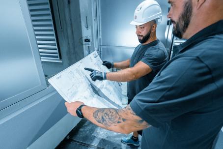
We are committed to providing you with an option to modify the appearance of the technical buildings as part of the implementation process.
OPERATIONAL AND SUPPORT SERVICES
We offer comprehensive support services with our transformer stations at maintenance, rehabilitation and modernisation.
We will find the optimal solution for your project. Ask our sales and technical representatives for advice or a no-obligation price offer.


